Zusammenbau der aktuellen goDMD V2 mini:
Bauanleitung für die goDMD V2 mini
Weitere Galerien
Kommentare deaktiviert für Bauanleitung für die goDMD V2 mini
Setup menu for version 2
The firmware for the new version 2 (rgb) features a completely refactored setup menu. Menu can be accessed via remote control or via menu button (backside of the controller board).
To enter the menu simply press “EQ” on the remote control or press the button for more than 1,5 seconds.
For button control of the menu there is always one of the four functions on the lower bar highlighted:
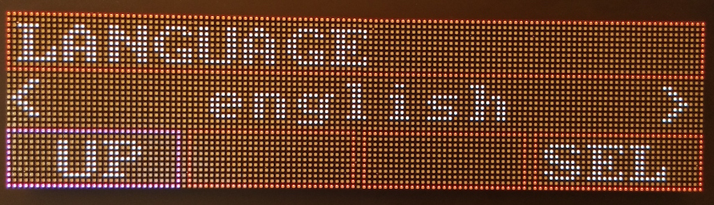
Short button click moves highlighted button to next, intermediate click activates current button, long click leaves menu.
With the remote control you can use the number buttons as arrows to navigate, so 4 and 6 go back and forth, 2 goes up and 5 selects. Whenever a value can be increased or decreased use the plus and minus buttons on the remote repsectively.
Veröffentlicht unter Allgemein
Kommentare deaktiviert für Setup menu for version 2
Firmware release for stm32 / color version / Connections
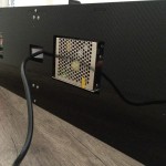
There is a new version of the new colored firmware available. The controller is based on the stm32f4 disco board, shields can be bought in the shop.
See https://bintray.com/sker65/godmd-stm32/Firmware
Connections
To get full functionality you have to connect several “sensors”:
- IR Receiver for a ir remote control
- DHT sensor for temperature and humidity
- PIR for detecting persons near the clock
See goDMD v2-Sensors pdf documentation on how to connect these sensors.
Veröffentlicht unter Allgemein
2 Kommentare
Bauanleitung für die “kleine” Version
Diese Galerie enthält 36 Fotos.
Folgende Bilder zeigen den Aufbau / Zusammenbau der Version mit dem p2.5 er Panels:
Anschluss-Belegung der goDMD v2 / Pin2dmd
Für alle Bastler und Selfmade-Fanatiker hab ich in der Tabelle unten die Anschlussbelegung des / der Shields an den STM32F4 zusammen gestellt:
GPIO A
0 - Latch / Button Blue
1 - RowClock
2 - RowData
3 - OE
5 - CLK
6 - DATA

8 - USB_OTG_SOF (not used)
9 - USB_OTG_VBUS
10 - USB_OTG_ID
11 - USB_OTG_DM
12 - USB_OTG_DP
13 - DETECT DMD ST32
14 - ESP GPIO
15 - ESP RESET

GPIO B
6 - USART1 TX Max232 SMARTDMD
7 - USART1 RX Max232 SMARTDMD
12 - SD CS
13 - SD SCK
14 - SD - DO
15 - SD - DI

GPIO C
0 - RGB OE
10 - UART4 TX WIFI
11 - UART4 RX WIFI
14 - RTC OSC (Go-DMD) 32,768 kHz 2 x 6,8pF
15 - RTC OSC (Go-DMD)

GPIO D
0 - R1
1 - G1
2 - B1
3 - R2
4 - G2
5 - B2
6 - RGB Clock

12 - LED GREEN
13 - LED ORANGE
14 - LED RED
15 - LED BLUE

GPIO E
2 - RGB Row A
3 - RGB Row B
4 - RGB Row C
5 - RGB Row D
6 - RGB Latch
7 - Sensor 1 (Go-DMD: IR-Receiver)
8 - Sensor 2 (Go-DMD: PIR)
9 - Sensor 3 (Go-DMD: DHT)
10 - Button 1
11 - Button
12 - Second DIP
Diese Belegung gilt für ein STM32F4 mit RTC on Board. Wenn ein RTC Modul verwendet wird, dann nutzt dieses:
SCL - PB6
SDA - PB7
Veröffentlicht unter Allgemein
2 Kommentare
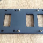
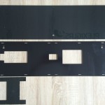
goDMD in Klein

Diese Galerie enthält 9 Fotos.
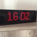
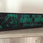
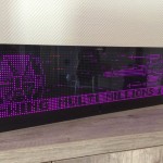
Dank der eifrigen Arbeit von Flipperforums Mitglied Guido gbausm gibt es nun auch ein Gehäuse für die goDMD in Farbe mit Panels mit 2,5mm Pixelabstand. Sie ist damit ziemlich genau halb so gross wie die Orginale goDMD und eignet sich hervorragend für … Weiterlesen
Weitere Galerien
Kommentare deaktiviert für goDMD in Klein
go DMD v2 RGB – Anleitung zum Zusammenbau
Diese Galerie enthält 37 Fotos.
Dank des Engagements des Forumsmitglieds gbausm gibt es bereits eine Bilder Galerie die den Aufbau / Zusammenbau der neuen RGB Version der goDMD Uhr zeigt: Was aktuell noch fehlt, ist der Sensor für Bewegung und Infrarot-Empfänger. Der Ausschnitt auf der … Weiterlesen
Weitere Galerien
Kommentare deaktiviert für go DMD v2 RGB – Anleitung zum Zusammenbau
goDMD in Farbe
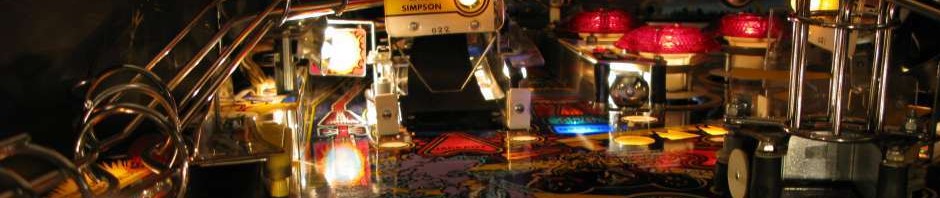
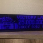
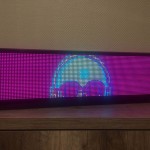
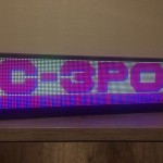
Auf Basis der Hardware des pin2dmd hab ich einen Prototype gebaut mit einer portierten Version der goDMD Firmware 1.11. Diese läuft nun auf einem ARM Cortex-4 Prozessor (STM32F4 Discovery Board) und steuert so auch RGB Panels mit bis zu 5 Bit Farbtiefe pro Farbe an (32k Farben gleichzeitig).
Ein Forumsmitglied der Flipper-Forums war so freundlich für P5 Panel (Pixel-Abstand 5mm) ein Gehäuse aus Acrylglas zu entwerfen. Es ist etwas grösser als die P4.75 Panels der alten goDMD, aber sieht genauso schick aus:


Sobald die Firmware den Beta Status hinter sich hat, werde ich das bestückte Shield (mit oder ohne STM-Board) im Shop anbieten. Gehäuse Bausatz kann auch über mich bestellt werden.
Das Board hat alternativ auch noch einen Eingang für reguläre DMD Anschlüsse für “echte” Pins und natürlich auch einen USB-Anschluss. Es kann also alternativ auch mit der Pin2dmd Firmware betrieben werden und dann als Flipper-Anzeige dienen z.b. Tournier-Anzeige in groß auf der Backbox.
Wie das aussehen kann, hatte ich schon einmal prototypisch – ohne Gehäuse – in diesem Video gezeigt:
Bei Interesse können auch Gehäuse für die kleineren Panels geordert werden, z.B. für P2.5 Panel, was der Anzeigengrösse des normalen DMDs ziemlich genau entspricht.
Veröffentlicht unter Allgemein
Kommentare deaktiviert für goDMD in Farbe
Pin2Dmd Editor
This is a new tool used in my new project pin2dmd, which is a RGB led panel nearly the size of a real pinball dmd for use within a real pinball machine or in a virtual pinball as well.
The driver board uses a stm32f4 discovery board, which has several connector to drive a hub75 rgb panel or a classic pinball dmd led replacement panel. Feed data in via usb from host computer or connect a real pinball machines dmd driver board output.
Further information see various threads on flippermarkt.de and vpuniverse.com:
- //vpuniverse.com/forums/topic/2219-pin2dmd-color-pindmd-compatible-interface-with-led-rgb-color-dmd/
- //www.flippermarkt.de/community/forum/showthread.php?t=160762
- //www.flippermarkt.de/community/forum/showthread.php?t=163144
- maybe some more on pinside
This page is about the editor for use with pin2dmd to define palettes and keyframes switching palettes export then to the driver board online via usb or “offline” via fila on sd card mainly for use in a real pinball machine.
There is also a more sophisticated manual on the pin2dmd website.
First to make it more concrete I’ve recorded a screencast to show the new functionality of pin2dmd editor.
You will always find the actual versions (mac and win / 32 and 64 bit) of the editor here.
Old Changelog:
v1.0.14:
- reenable rename of keyframes and anis
- added licensing for pin2dmd export
- added support for masks
- changed export format to new 2.X firmware of pin2dmd
v1.0.12:
- reenable export of foo.ani (goDMD)
- minor bugfix on loading animations
v1.0.11:
- lots of minor bugfix regard project load / save / export
v1.0.9:
- Bugfix device config, default palette
v1.0.8:
- added device config, writing pin2dmd.dat
v1.0.7:
- drawing improved, big refactoring
v1.0.5:
- bugfixes for smartdmd palette import
v1.0.4:
- minor bugfixes in UI
v1.0.3:
- fixed load project bug
v1.0.2:
- Bugfix: first defined keyFrame was not saved
- Bugfix: Load / Save could hang if animation was stopped.
- Improvement: First implementation of USB tooling to directly communicate to pin2dmd (untested)
Recording is outdated and refers to an older version of the editor.
To get such recordings from a vp session there is also a tutorial see here //go-dmd.de/2015/03/17/go-dmd-animationen-aufnehmen-mit-visualpinball/ (german of course, but with google translations integrated in the page)
And to make it short its just:
- copy the right vpinmame.dll into the pinmame directory
- create a c:\tmp directory
- play your favourite pinball and do a really go play to include as many dmd frames as possible.
- open cmd.exe, goto c:\tmp. rename dump.txt to my-drwho-recording.txt (or whatever) and compress it with gzip.
- This is the kind of recording to editor can laod.
Have fun.
I’ve added a recorded video tutorial for capturing dmd scenes as well:
Veröffentlicht unter Anleitungen
13 Kommentare
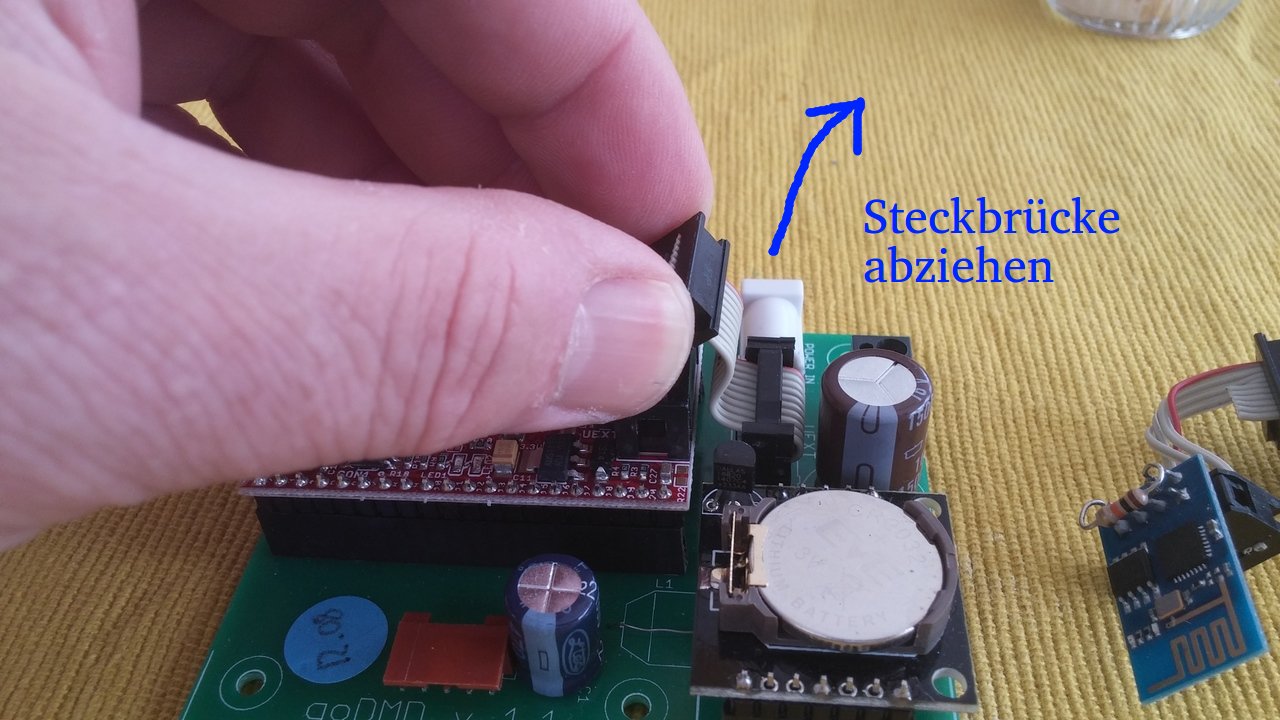
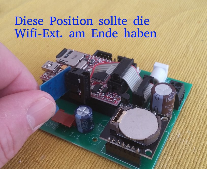
goDMD – Einbau der Wifi-Extension
Nachdem mit ein Nutzer gefragt hatte wie der Einbau der Wifi-Extension geht, will ich hier eine kleine Anleitung nach liefern.
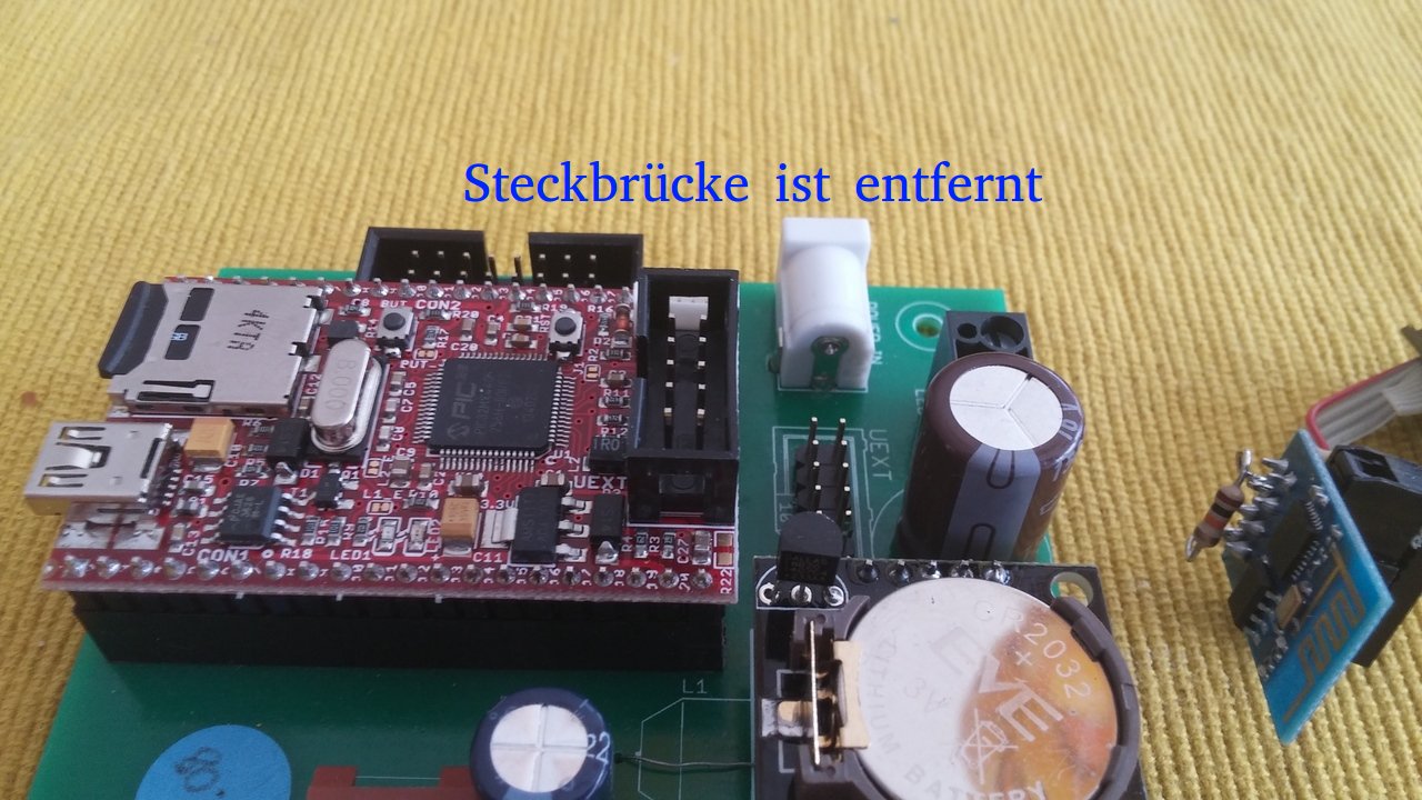
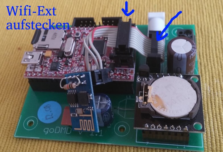
Die Wifi-Extension ersetzt die kleine Flachbandkabel-Brücke von der aufgesteckten Pinguino Platine. Hier sieht man die Schritte:
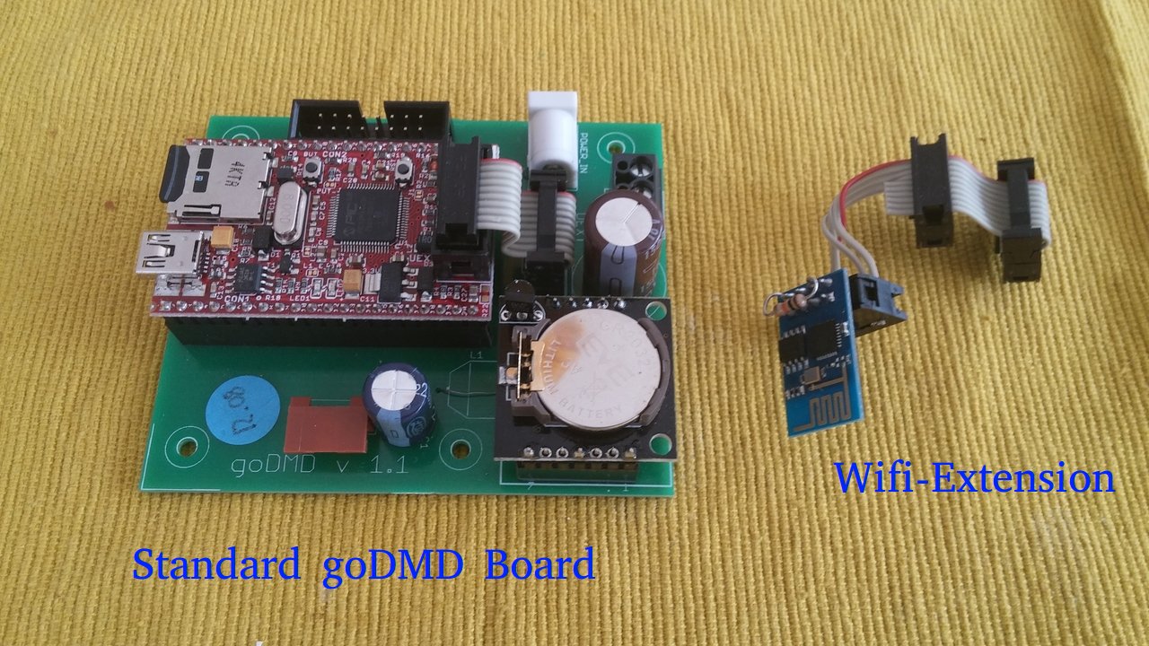
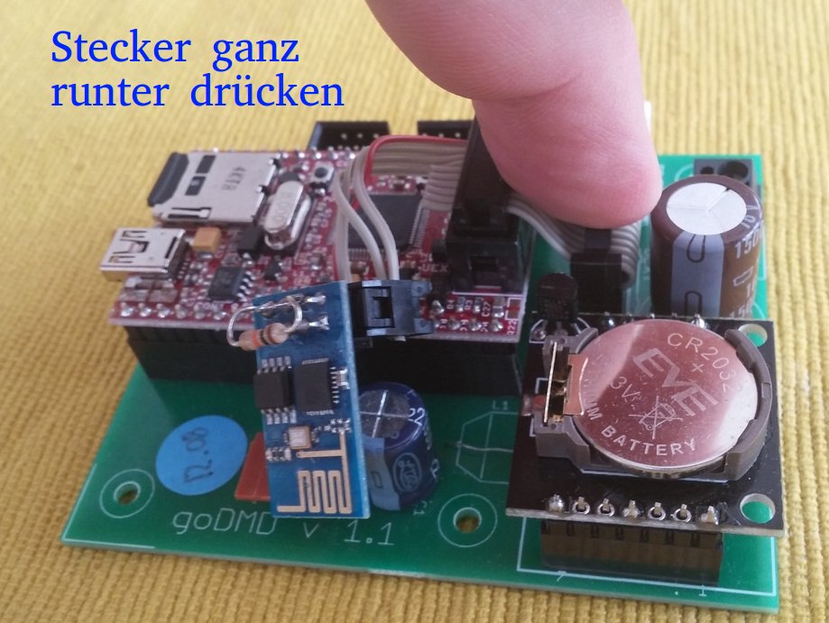
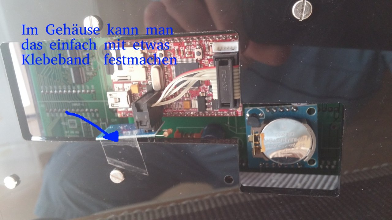
Hoffe mal diese Erklärung hilft beim Umbau.
Veröffentlicht unter Anleitungen
Kommentare deaktiviert für goDMD – Einbau der Wifi-Extension

